KVM Switchinator
📁 Source code: View on GitHub →
I’m no stranger to producing complex solutions to simple problems - and the KVM Switchinator is no different! I run a somewhat complex desktop setup whereby my two monitors are controlled by a KVM, each, so I can switch between four potential inputs per screen. This makes it so I can have my home and work machine as well as two others (one set up with ports on the outside of the desk so I can wire up a box quickly and temporarily) to the same monitors. This is awesome for when I’m bootstrapping a new machine so I can keep the right hand monitor on the bootstrap screen while tooling around with the keyboard, mouse, and left monitor on my main machine.
You may say, “That sounds pretty sweet. What was the problem?” - and you’re right. It is sweet, but the problem was simple. Having two 4-way KVMs sitting on the desk costs a lot of real estate. I really don’t like having a crowded desk - only stuff that I actually use should be on the desk.
While it took ages to find a KVM that fits all my needs, I finally settled on a TESmart HKS0401B2U after experimentation. This one features the important bits:
- Hotkey switching (double-tap scroll lock and then the number to switch to)
- IR switching (use the remote to select the target)
- USB passthrough (plug in any USB 2 device and it switches with the KVM)
- HDMI in and out w/ 4k@60Hz (I actually only use 2k@60Hz)
- EDID emulation (for when a PC comes online or the screen switches, the machine still “sees” the monitor)
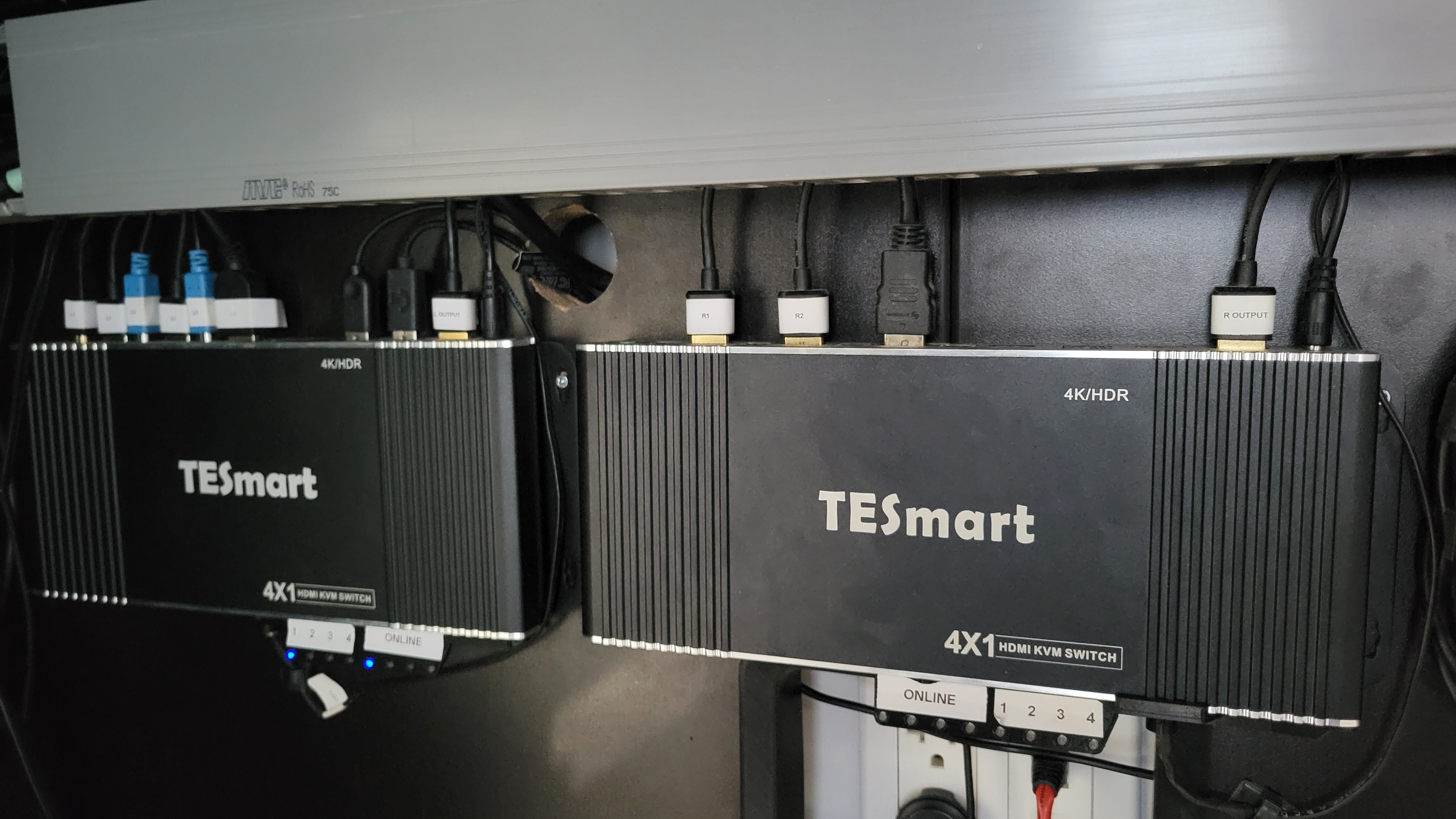
While it sometimes has issues, and I’ve had to even replace one (more on that in a moment), it’s been a really solid solution. Unfortunately, because of how they are set up, they are quite wide, and take up a lot of space on my desk.
I first started by 3D printing up a simple vertical stacking mount so they’d only take up the width of a single unit at double the height. This worked well, but I still didn’t want that much desk real estate taken up, so I decided to relocate the devices under the desk.
This is when some “incompatibilities” came out:
- Only one keyboard is connected, so the hotkey switching controlled only the left monitor. This meant the physical button (or IR remote) to switch was needed
- Both devices use the same IR codes, so pointing the remote at them would switch both devices
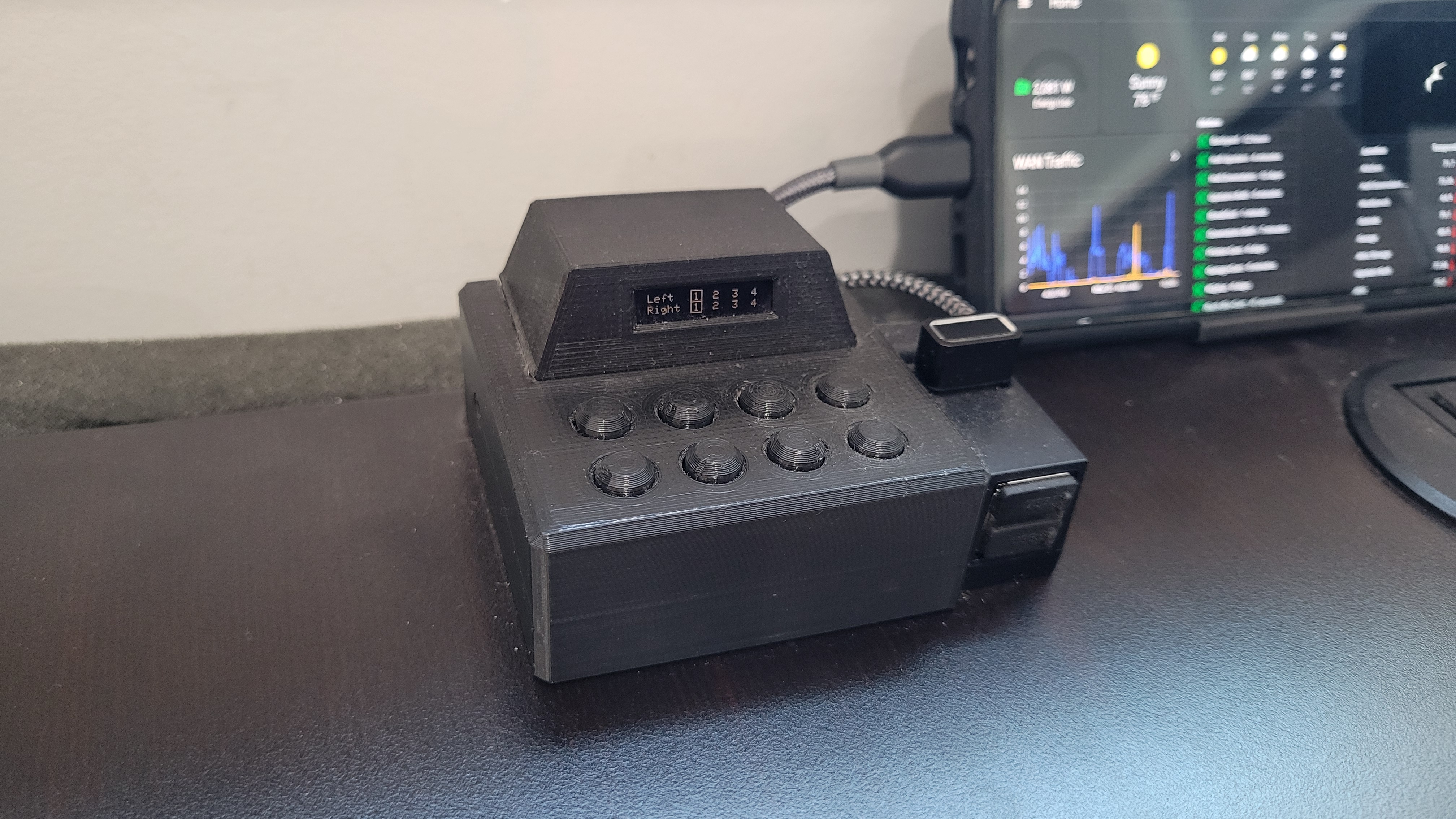
I decided the solution was to use a small desk-mounted controller that would trigger each KVM independently via IR, and some 3D printed housings to keep it all together. The unit on the desk would have a small LED screen showing which input each KVM is set to with eight buttons to switch the left or right KVM to the desired input.
Learning to read IR codes
Through the course of creating the system, I needed to take a short detour to identify the IR codes used to switch which KVM input is active. Many years ago, I played around a lot with LIRC and knew that if you had an IR reader, it is easy to have it dump the raw IR signals that are sent to it. Unfortunately, I didn’t have a Linux IR reader handy anymore (got rid of it when I moved away from MythTV) so I decided to just toss an IR receiver on the board. This made for a decent plan because I could learn IR codes from the same Arduino library I want to use to emit IR codes. All I needed was a bit of code to do the learning, and I was set! So now, even while the Switchinator is running, all you have to do is point to the IR receiver and press a button - the human readable version and the source code version will be printed to serial.
Fitting it all onto the board
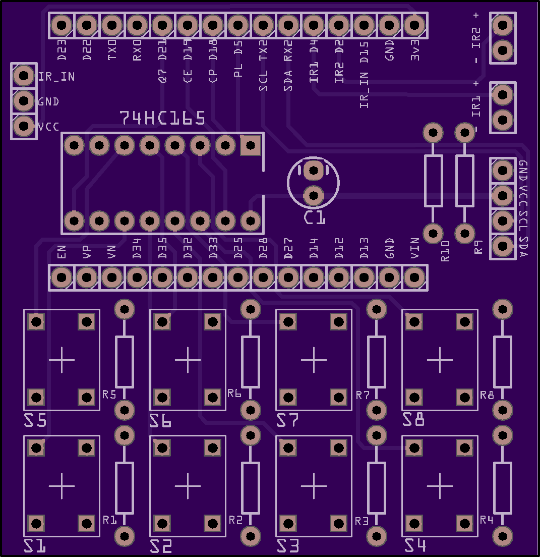
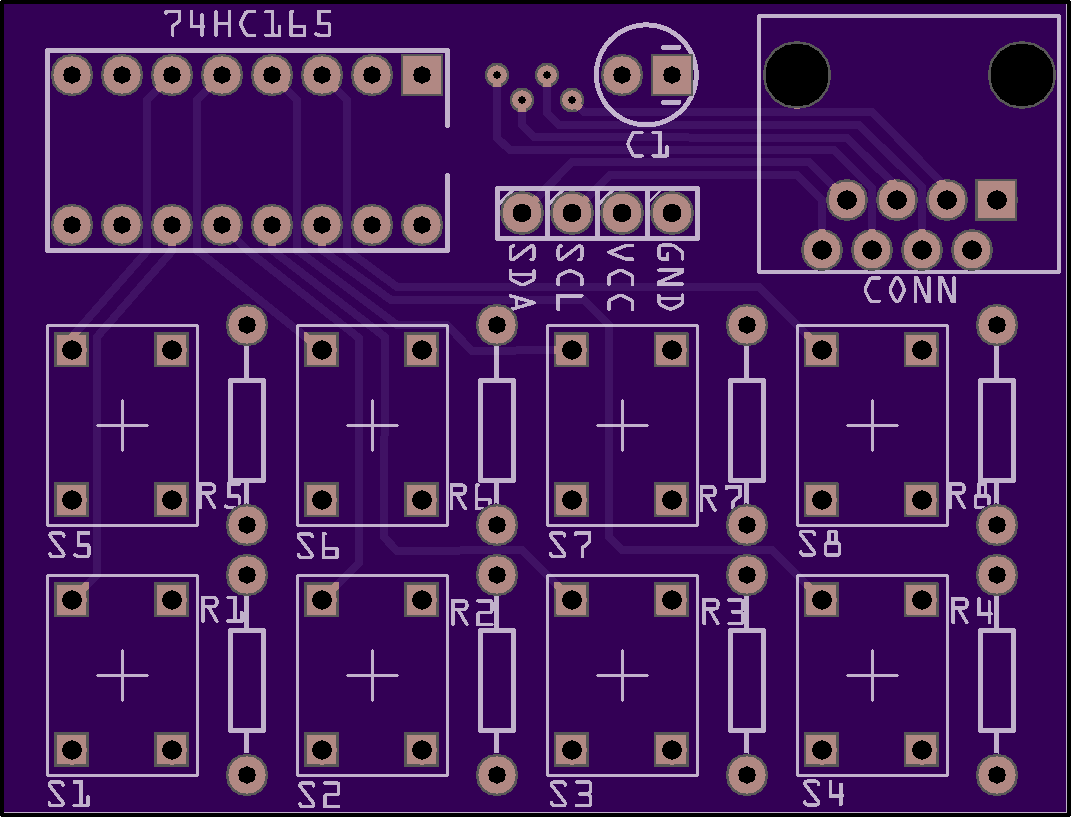
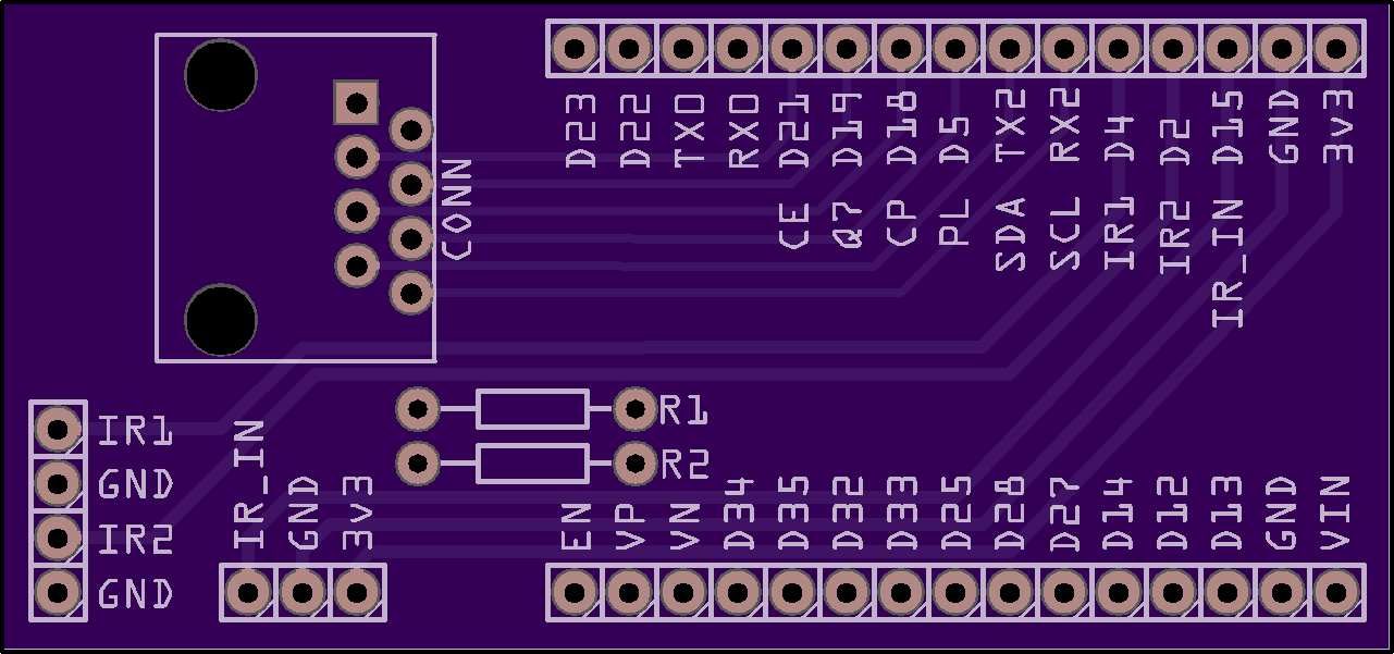
The ESP32 dev board that I selected (well, that I had sitting around in inventory) has 14 total pins (D13, D14, RX2, TX2, D18, D19, D21, D22, D23, D25, D26, D27, D32, D33) that can be used for whatever you want. This in itself posed a problem because I needed 13 pins to start with:
- 8 pins to detect button presses
- 2 pins for IR emitting
- 1 pin for IR receiving
- 2 pins for I2C to the OLED screen
For the first design, where I wanted to have separate boards, this was a nonstarter. I wasn’t about to go out trying to find commodity 14 pin wiring and connectors, so the solution was to use the famous HKS0401B2U parallel load shifter chip. This allows one to wire up 8 switches to the chip and read the status of all 8 switches as a single byte of data all at once (well, kinda - at once as far as we humans will know). This took the required 8 pins down to only two - and meant that I wouldn’t have to deal with connecting 14 total pins, much less how to route 8 inputs to the board. Nice!
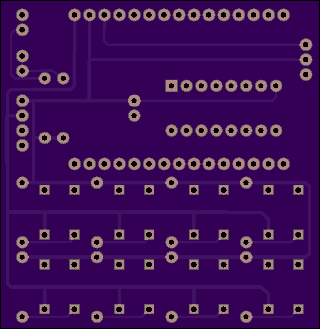
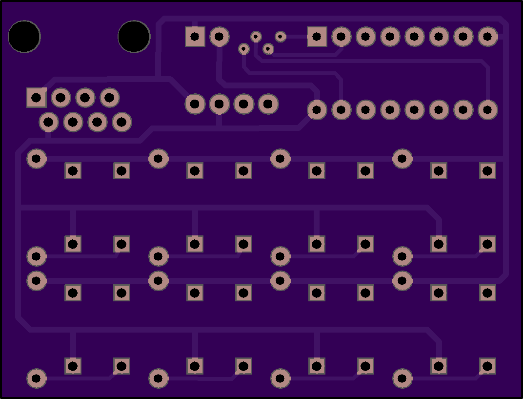
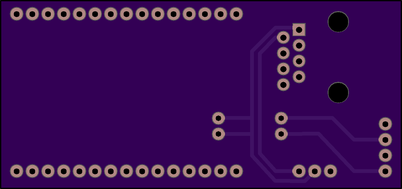
Circuit Boards
Models
The modeling wasn’t especially challenging - just simply tedious. Per usual, each piece required about three prototypes before everything was dialed in and fit well.
The board mount, case, and screen are all designed to slot into each other with a simple friction fit. This enables later disassembly form maintenance or whatever. The buttons sit freely in the housing so button presses don’t have to overcome friction or potentially bind on the case itself.
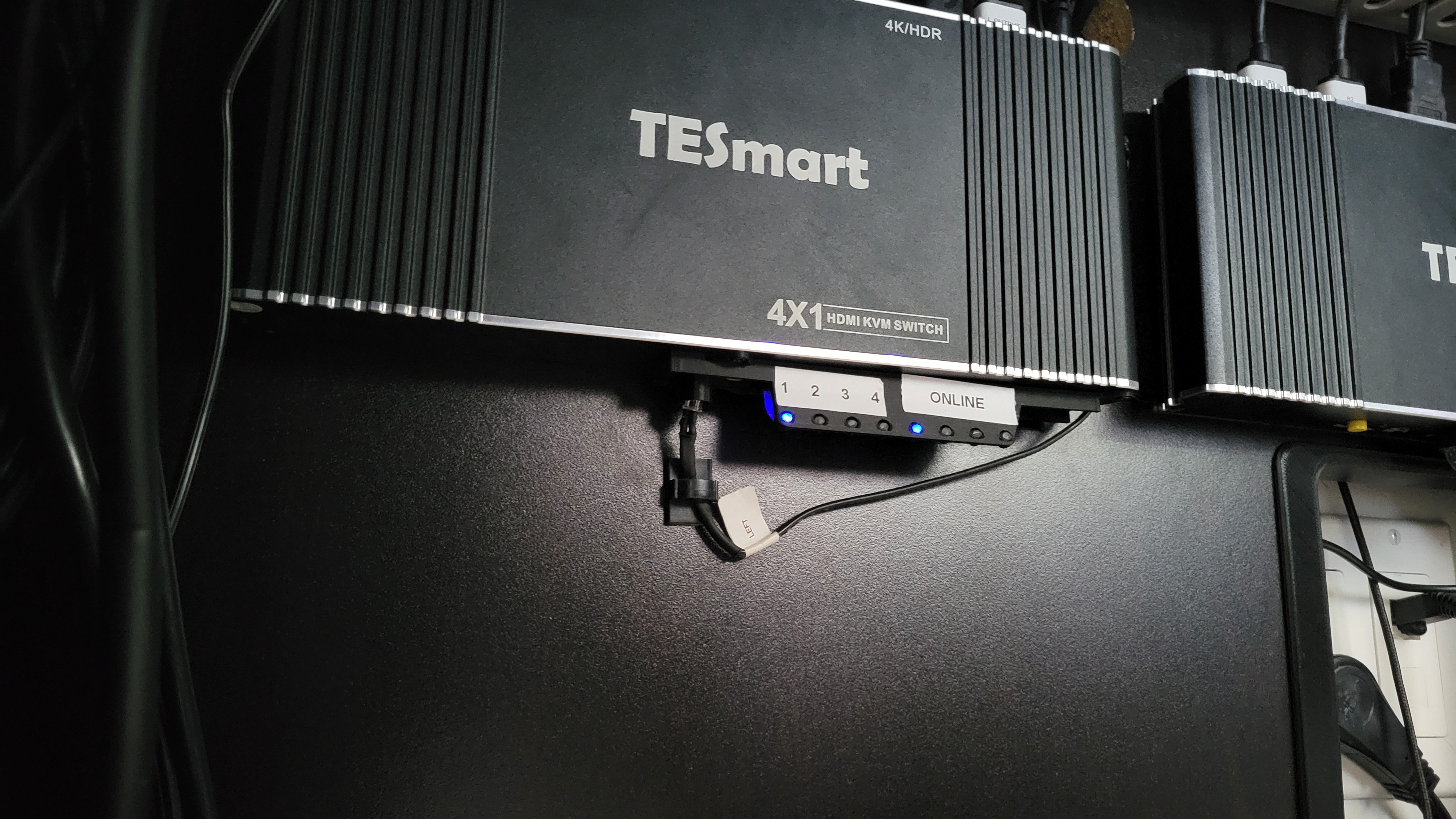
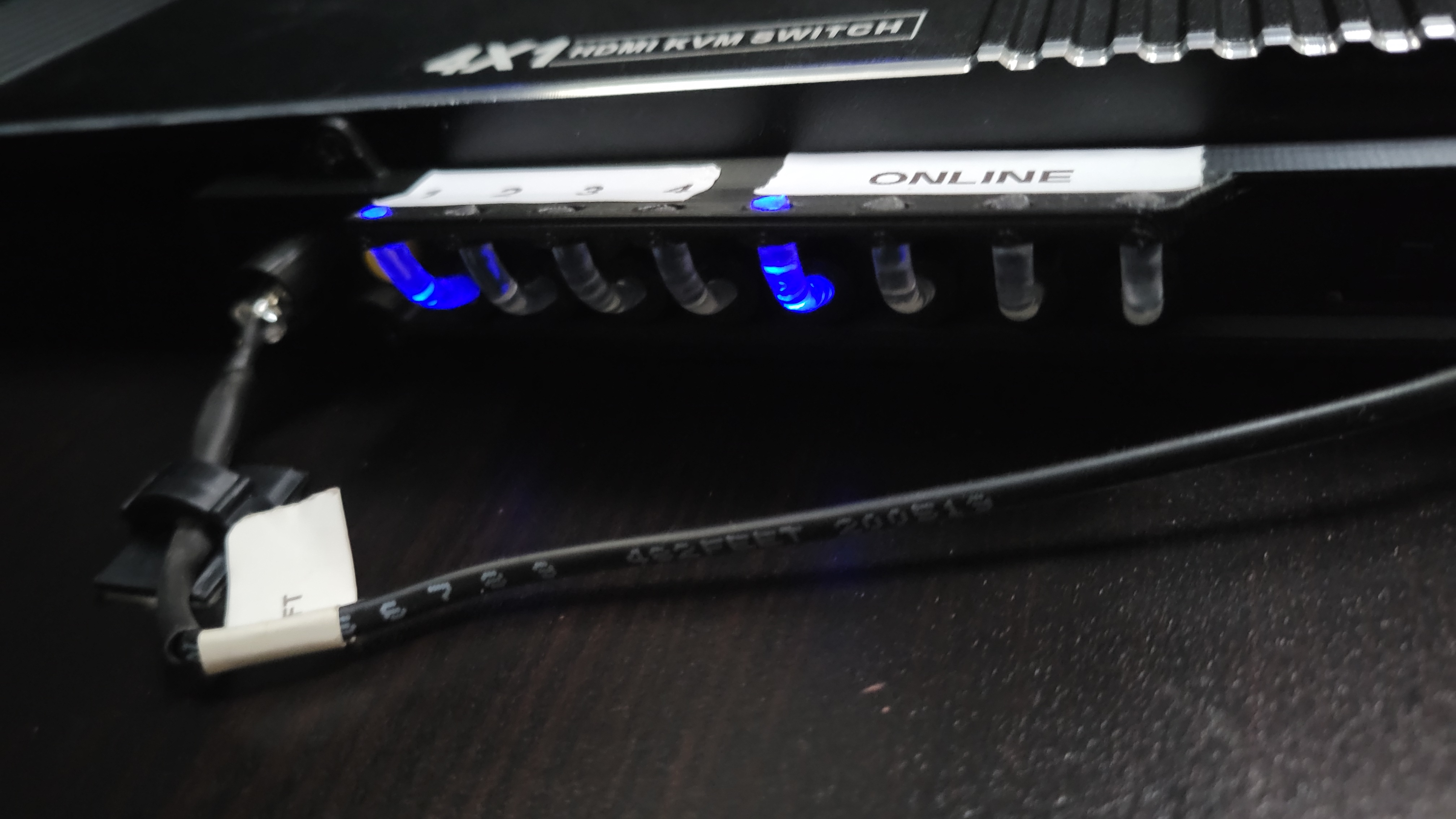
Identifying the exact dimensions of the screw holes, buttons, LEDs, and IR port of the KVM itself was the most annoying. I’m sure there’s a straight forward way (now that I’m writing this in 2026 and AI assisted workflows are very prevalent) where I could have taken a picture of the front or scanned it on my flatbed scanner to get much more precise dimensions… but I never quite settled on a great workflow aside from using calipers, printing, testing, and adjusting. The key features for the KVM face cover are:
- Holes for mounting that align with the actual faceplate’s holes - just unscrew the faceplate, put it on top, and screw it back in.
- An angled bracket with light pipe holders on each side so I can see the LEDs of the KVM - when mounted on the wall of my desk, the LEDs face down, so status isn’t visible at a glance
- A receiving “tube” for the IR emitter so IR signals sent to the specific KVM don’t “leak” out and trigger the other KVM
Oh, and the fun part - remember how I said that one of the KVMs failed after a few years and I needed to replace it? They changed the front plate and where everything sits - so now there are two versions of the face plate!